You may also like

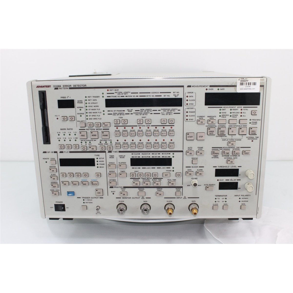
Advantest D3286 BER Error Detector

The Advantest D3186 Pulse Pattern Generator/D3286 Error Detector offers waveforms operating frequency range from 150 Mbps to 12.5 Gbps.

Option 70 is used to select data comparison pattern from PRBS, WORD and Frame

Click the PDF Specification for further information.

Read moreShow less
USD $547.00
5 1
,
5/ 5
Yes, we have 3 in stock
Condition
Used
Reference:
D3286_70
Description

Advantest D3286 Bit Error Rate Detector C/W Option 70

Error detection with area specification effective for Sonet and SDH frame and ATM cell measurement . Burst data measurement effective for loop-back test. Auto search function which adjusts the most appropriate timing and voltage

Monitor output of data and clock. FD drive for storing measurement results and setup data

GUI environment realizing easy and legible operating environment

Specifications: unit includes Option 70 (Mixed Pattern Generation)

  • Operating Frequency Range: 150 MHz to 12 GHz
  • Measurement Input
  • Data Input
    • Input format:  DC termination, DC coupling
    • Code: NRZ
    • Polarity: Logical inversion possible
    • Input amplitude: 0.1 Vp-p to 2 Vp-p
    • Threshold level:
      • Setting range -2.040 V to + 2.040 V
      • Setting resolution: 0.001 V steps (with 0 V terminal voltage)
      • Setting range: -1.850 V to -0.750 V
      • Setting resolution: 0.001 V steps (with-2 V terminal voltage)
    • Terminal voltage: -2 V/0 V (GND)
    • Input impedance: Approx. 50 ?
    • Connector: 2.92 mm (plug)
  • Clock Input
    • Input format: DC termination, AC coupling
    • Duty ratio: 50% ±5%
    • Polarity: Identified at rise edge
    • Variable delay: ±400 ps 1 ps steps (at monitor output)
    • Input amplitude: 0.5 Vp-p to 2 Vp-p
    • Terminal voltage: -2 V/0 V (GND)
    • Input impedance: Approx. 50 ?
    • Connector: 2.92 mm (plug)
    • Input waveform: Sine wave or rectangular wave
  • Auto Search Function
    • Automatically finds the optimum values for data input threshold level and clock input delay.
  • Trigger Signal Output
    • Output Signal:  Can be selected as either clock synchronization or pattern synchronization
    • Clock synchronization (1/32 CLK): Clock frequency 1/32 divided output
    • Pattern synchronization (PATTERN): Varies output position to any position in 16 bit units
    • Output level: HIGH level 0 V ±0.2 V, LOW level -1 V ±0.2 V
    • Load impedance: 50 ? to 0 V
    • Connector: SMA
  • Auxiliary Output
  • Monitor Output
    • Data monitor: Outputs data input through amplifier
    • Load impedance: 50 ? to 0 V
    • Connector: 2.92 mm (plug)
    • Clock monitor: Outputs clock input through amplifier and variable delay line
    • Load impedance: 50 ? to 0 V
    • Connector: 2.92 mm (plug)
  • Error Output
    • Direct output
    • Rate: 1/32 of clock input
    • Signal form: 32 phase logical sum
    • Code: RZ
    • Output voltage: HIGH level -0.0 ± 0.3 V
    • LOW level -1.0 ± 0.3 V
    • Load impedance: 50 ? to 0 V
    • Connector: SMA (jack)
    • Stretched output
    • Level: TTL positive pulse
    • Pulse width: Approx. 100 ns
    • Load impedance: 50 ? to 0 V
    • Connector: BNC (jack)
  • External Gate Input
    • Function: Controls measurement start/stop
    • Input level: 0 V/-1 V
    • Input impedance: Approx. 50 ? to 0 V
    • Connector: BNC (jack)
  • External Alternate Input
    • Function: Switches between patterns A and B in alternate mode. Pattern A at HIGH level, pattern B at LOW level.
    • Input level: 0 V/-1 V
    • Input impedance: Approx. 50 ? to 0 V
    • Connector: BNC (jack)
  • Patterns
    • Same as for the D3186 Pulse Pattern Generator
  • Time Reference Clocks: Internal, external, selected automatically
    • Internal clock stability: 10 ppm/year
    • External clock input: 10 MHz, 1 Vp-p , AC coupled
    • Connector: BNC (Jack)
  • System Functions
  • Printer: Measurement results can be output to an external printer
  • External printer interface:
    • Standard specification: Centronics specification
    • Connector: 36 pin micro ribbon
  • File Function: Same as for the D3186 Pulse Pattern Generator and possible to save measurement results
    • Measurement results: MS-DOS®text format
  • Remote Control
    • Interface: GPIB (IEEE 488-1978)
  • Master/Slave Function
    • Function: When used together with the D3186 Pulse Pattern Generator, allows the pattern settings of the D3186 and D3286 to be interlocked.
    • Connection method: Connected by GPIB cable, through each
    • GPIB connector
  • Panel Lock: Can lock all condition settings except power ON/OFF, panel lock ON/OFF, GPIB Local return, rear panel DIP switch settings, and buzzer volume level.
  • General Specifications
    • Numerical value display: Green 7 segment LED display
    • Set conditions memory: After power has been ON for 12 hours, retained at least 2 weeks (backed up by secondary battery)
    • Operating temperature range: 0 °C to +40 °C +20 °C to +30 °C (Option 72)
    • Operating humidity range: 40% to 85% RH
    • Storage temperature range: -20 °C to +60 °C
    • Storage humidity range: 30% to 85% RH (without condensation)
    • Power: AC 100 V to 120 V, AC 220 V to 240 V (switches automatically) 48 to 63 Hz, sine wave
    • Power consumption: 500 VA max.
    • Mass: 32 kg max.
    • External dimensions: Approx. 266 (H)×424 (W)×550 (D) mm

*Specifications may change without notification.

Read moreShow less
Product Details
D3286_70
Terms and Conditions

Settings

Click for more products.
No products were found.

Menu