Keithley 2510 Source Meter
USD $2,195.00

JDSU SWS20008 SWS-CD Optical Modulator
USD $1,195.00

JDS SWS20009A SWS-OMNI Receiver
USD $1,095.00


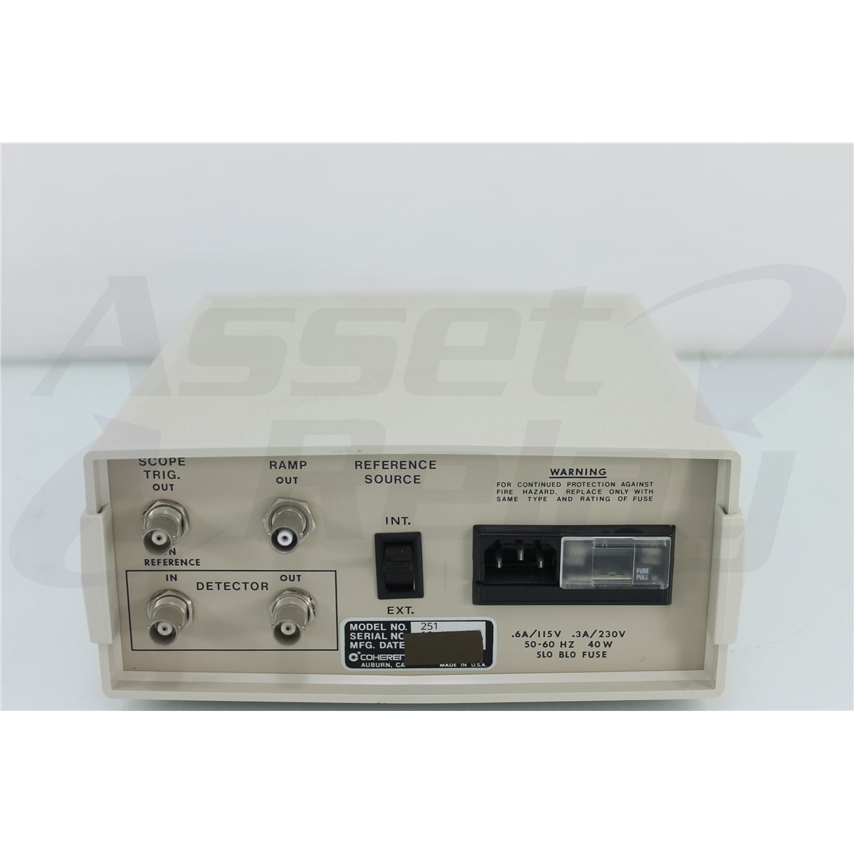
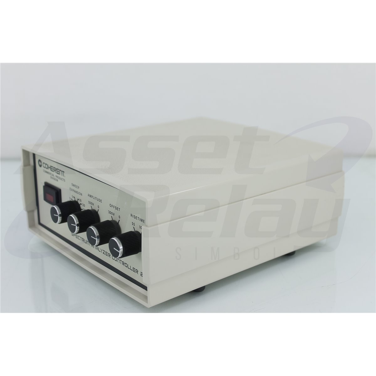
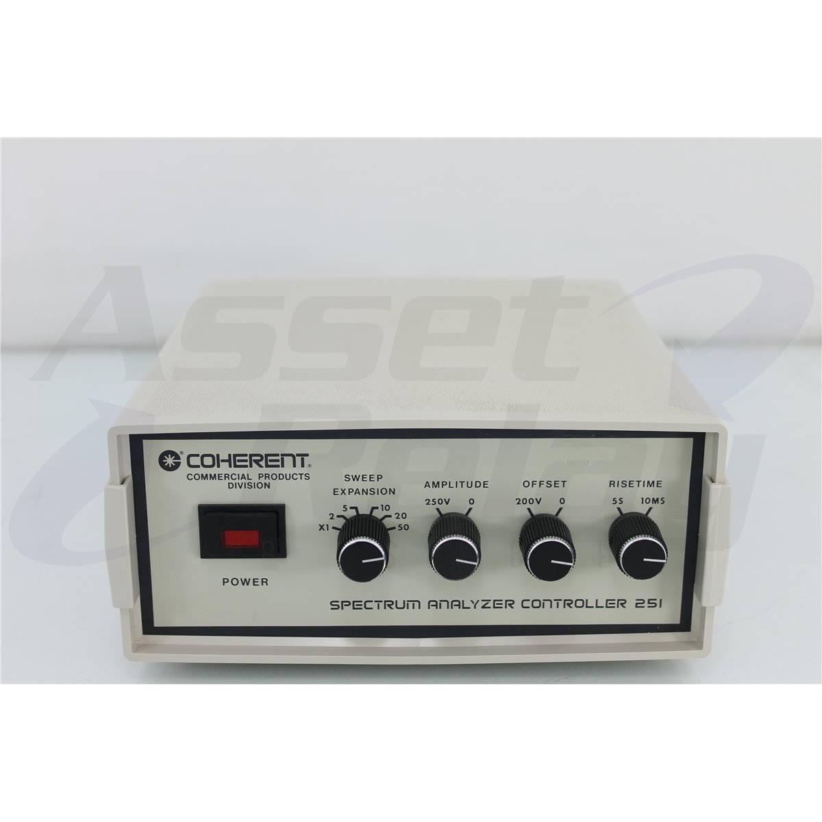
The Model 251 Spectrum Analyzer Controller is designed to be used in conjunction with Model 216 or 240 Optical Spectrum Analyzers. In the internal ramp (INT) mode, the Model 251 moves one of the two spherical mirrors inside the Spectrum Analyzer by providing controlled modulation of a ramp voltage to a piezoelectric crystal. This ramp has a continuously variable amplitude, offset and risetime, all adjustable by front panel controls. The Detector Output of the Spectrum Analyzer is coupled to an internal amplifier in the Model 251. (This signal represents the spectral profile of the input light beam.) An External Trigger signal for the user's oscilloscope which controls blanking of the output signal during the ramp retrace is also available as an output. When used in external (EXT) mode, the MODEL 251 provides an output signal which is directly proportional to the input signal for external control of the ramp shape and timinig. The MODEL 251 is used in external (EXT) mode to drive the referencer mirror of an interferometer for computerized wavefront analysis by 70/EE or 70/S.
| Specifications | |
| Ramp Generator | |
| Input Voltage | 100, 120, 220, 240 VAC, 50-60Hz |
| Total Power required | Approximately 15 watts |
| Rise Time of Ramp | 10 ms - 5 sec±10% |
| Ramp Amplitude | 0-250 Volts |
| DC Offset | 0-200 Volts |
| Fall Time of Ramp | 10 ms±10% |
| Ramp Linearity | 1.5% |
| Sweep Expansion Ranges | 1x, 2x, 5x, 10x, 20x, 50x |
| Detector Amplifier | |
| Input Resistance | 100 Ω |
| Max. Input Current | ±100 µa |
| Max. Input Voltage | ±10 mv (Rs<100Ω) |
| Output Resistance | 10 KΩ (amplifying) 300 KΩ (blanking) |
| Blanking Attenuation | Typical 80 dB |
| Cust Off Frequency | 80 Khz (typical) |
Please sign in first.
Sign in