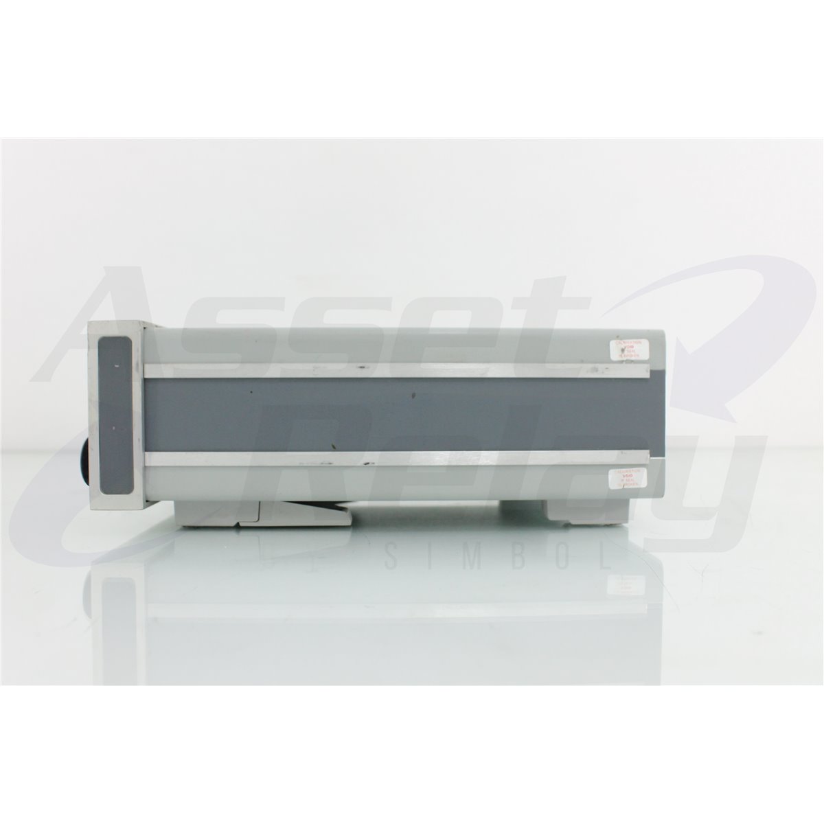
JDS JDSU Viavi MOPM-C1PMH2 Optical Power Meter
Gentec Solo2 Single Channel Power Meter
The ILX Lightwave FPM-8200 is a precision fiber optic power meter with an integrated InGaAs detector for measurements from 800 nm to 1600 nm. It provides a -75 dBm to +1.5 dBm optical measurement range, more than 75 dB of dynamic range at 1300 nm, ±2.5% reference-condition accuracy, and high linearity across its supported range. Fast 50 ms sampling, selectable digital filtering, Save and Recall functions, an LED alignment bar graph, 0 V to 10 V analog output, GPIB control, and interchangeable connector adapters support laboratory, production, component characterization, and automated optical testing.
Download the ILX Lightwave FPM-8200 Specification Sheet (PDF)
Request Pricing
The ILX Lightwave FPM-8200 is a precision fiber optic power meter designed for accurate optical power measurements across wavelengths from 800 nm to 1600 nm. It combines an integrated InGaAs detector, more than 75 dB of dynamic range at 1300 nm, fast data acquisition, high linearity, NIST-traceable calibration, and flexible system interfaces in a compact benchtop instrument.
The FPM-8200 supports absolute optical power measurements, relative measurements, insertion-loss testing, attenuation measurements, optical source characterization, component evaluation, and production quality control. Its broad wavelength range covers many common multimode and single-mode applications, including systems operating near 850 nm, 980 nm, 1300 nm, 1310 nm, 1480 nm, and 1550 nm.
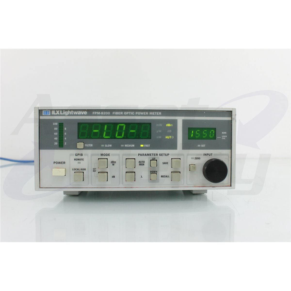
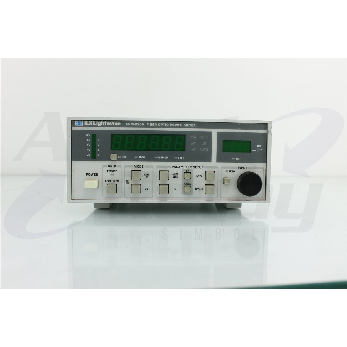
The instrument incorporates a five-digit power display, a four-digit wavelength display, and an LED power-level bar graph. Optical power can be displayed in logarithmic or linear units with 0.001-unit resolution. Three digital filter settings allow users to balance display speed and noise reduction, while the bar graph provides fast visual feedback during optical alignment and system optimization.
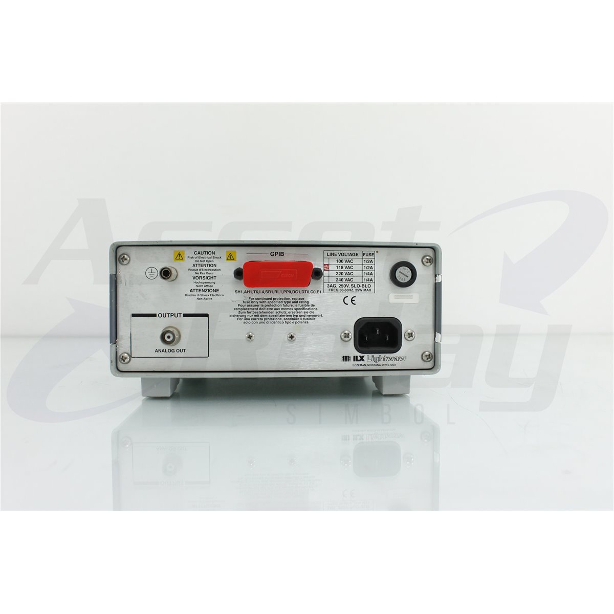
For automated testing, the FPM-8200 includes a GPIB interface and rear-panel analog output. Save and Recall functions allow complete instrument configurations to be stored and restored, helping users repeat established measurement procedures in laboratory and production environments.
The FPM-8200 covers an optical wavelength range from 800 nm to 1600 nm. This broad response allows one instrument to support many fiber optic, laser diode, telecommunications, datacom, and photonics applications.
The wavelength is entered through the front-panel controls and displayed on a dedicated four-digit LED display. Wavelength can be selected in 1 nm increments, allowing the instrument to apply the appropriate detector correction for the optical source being measured.
For best accuracy, the selected wavelength should correspond to the actual center wavelength of the source. Entering an incorrect wavelength can introduce measurement error because the responsivity of the InGaAs detector varies across the spectrum.
The specified accuracy range extends from 1000 nm to 1600 nm. Measurements from 800 nm to 1000 nm remain supported, but the minimum specified power level and noise performance differ from those available at longer wavelengths.
The documented optical detector range is -75 dBm to +1.5 dBm from 1000 nm to 1600 nm. At wavelengths from 800 nm to 1000 nm, the specified minimum measurable power is -70 dBm.
The front-panel power display covers values from -80 dBm to +5 dBm. This display range is broader than the range over which the detector’s specified accuracy and linearity apply and should not be interpreted as an expanded guaranteed measurement range.
The upper damage threshold is +10 dBm. Optical input power should be verified before connection whenever the source level is unknown. External attenuation should be used when the signal could exceed the detector’s supported operating range.
The FPM-8200 uses an integrated indium gallium arsenide detector. InGaAs technology provides useful sensitivity across near-infrared wavelengths commonly used in fiber optic communications, laser diode testing, photonics research, and optical component manufacturing.
Because the detector is built into the instrument, an external optical head is not required. The selected connector adapter or bare-fiber fixture directs light into the internal detector assembly.
The complete optical setup must remain within the supported numerical aperture, power, wavelength, and connector conditions. Detector response can be influenced by beam placement, fiber numerical aperture, adapter condition, connector contamination, and calibration status.
The FPM-8200 was designed for calibration traceable to standards maintained by the National Institute of Standards and Technology. Wavelength calibration is performed at 10 nm intervals across the supported range.
Reference-condition accuracy is specified at ±2.5%. The reference conditions include a temperature of 23 °C ±2 °C, a wavelength from 1000 nm to 1600 nm, a 1.1 mm optical spot diameter, and an incident power of -20 dBm or 10 µW.
Under the documented operating conditions, accuracy is specified at ±5%. These conditions include operation over the supported temperature range, wavelengths from 1000 nm to 1600 nm, and fiber numerical aperture below 0.3.
Measurement uncertainty applies across the supported power range and includes calibration traceability. A current calibration should be used when documented or traceable optical measurements are required.
The FPM-8200 provides linearity of ±0.015 dB and ±2 pW. The linearity specification describes total variation from a straight-line detector response across the applicable measurement range when measurements are made in autorange mode at the documented temperature.
High linearity allows the instrument to compare optical signals across a wide power range without introducing substantial range-dependent error. This is valuable for attenuator testing, insertion-loss measurements, optical source characterization, and component transmission measurements.
Power-range limits are defined by the linearity specification using fiber with a numerical aperture of 0.11, such as compatible SMF-28 single-mode fiber. The maximum linear power limit can be higher when wider-numerical-aperture fiber is used, subject to detector and system limits.
From 1000 nm to 1600 nm, optical noise is specified below 2 pW peak to peak. From 800 nm to 1000 nm, noise is specified below 4 pW peak to peak.
These noise values are measured over one minute using the medium filter setting. Low noise supports measurements of weak optical signals and small changes in component transmission.
Environmental stability remains important at low power levels. Stray light, connector movement, changing temperature, static discharge, and contamination can affect measurements near the lower end of the instrument range.
The FPM-8200 provides a measurement sample period of 50 ms, corresponding to as many as 20 readings per second. This acquisition speed supports production measurements, optical alignment, source monitoring, automated test sequences, and observation of changing optical power.
The GPIB data-transfer capability is faster than the measurement sample rate, allowing the instrument to transfer readings without becoming the principal limitation in many automated systems.
Actual acquisition timing can depend on autoranging, digital filtering, computer communication, software overhead, and whether the optical power crosses between detector gain ranges.
The FPM-8200 includes three digital display-filter settings. The fast setting uses one measurement and updates in 0.05 seconds. The medium setting averages ten measurements and updates in 0.50 seconds. The slow setting averages 100 measurements and updates in five seconds.
The fast filter is useful for alignment and rapidly changing signals. Medium filtering provides a balance between response time and noise reduction. Slow filtering provides the greatest averaging for stable low-level measurements.
The documented update rates apply when readings remain within the same gain range. Additional time may be required when the instrument changes ranges during autoranging.
The optical power display uses a five-digit, seven-segment LED and supports logarithmic or linear measurement modes. Display resolution is 0.001 unit in either mode.
The wavelength input uses a separate four-digit, seven-segment LED display. The wavelength range extends from 800 nm to 1600 nm with 1 nm resolution.
Separate power and wavelength displays make it easier to verify the active correction wavelength while viewing the measured optical level.
A front-panel LED bar graph provides quick visual feedback of relative power within the selected gain range. Its resolution is better than 0.05 dB.
The bar graph is useful for optical alignment, connector optimization, component adjustment, source coupling, and locating the highest transmission point in an optical setup.
Unlike a numerical reading alone, the bar graph makes small directional changes easy to observe from a distance or in a darkened laboratory.
The FPM-8200 includes a zeroing function that compensates for background offsets across all seven detector gain ranges. Pressing the front-panel zero control initiates the zeroing process.
During zeroing, the zero indicator flashes and the power display blanks. The process can be cancelled, in which case the instrument returns to the gain-range offsets determined by the most recent completed zero calibration.
The optical input should be completely blocked from the signal and stray light during zeroing. The instrument should also be thermally stable before a precision zero operation is performed.
Save and Recall functions allow complete instrument states to be stored and restored from the front panel. This feature supports repeated measurements that use the same wavelength, display units, filtering, ranging, and related settings.
Stored configurations can improve consistency among operators and reduce setup time in production or laboratory workflows.
Recalled settings should be reviewed before a new device is connected, particularly when the expected optical power, operating wavelength, or connector configuration differs from the previous setup.
The FPM-8200 includes a GPIB interface for remote programming and readout. Functions accessible from the front panel can also be controlled through the interface bus.
GPIB communication allows the power meter to be integrated with laser diode controllers, tunable sources, optical switches, attenuators, temperature controllers, and other compatible instruments.
Automated applications can configure the wavelength, retrieve optical measurements, change filter settings, zero the detector, and coordinate readings with a larger test sequence.
A compatible LabVIEW instrument driver was available for system development. The GPIB cable, computer interface, software, and automation program should be considered included only when specifically identified in the product listing.
The rear-panel analog output provides a 0 V to 10 V signal with typical bandwidth from DC to 10 Hz. Typical output impedance is 1000 O.
The analog signal can be connected to a compatible strip-chart recorder, data-acquisition device, voltmeter, control system, or other external equipment.
The connected device should provide an appropriate input impedance and must not apply an external voltage to the analog output. Analog scaling should be verified for the selected power range before recorded values are interpreted.
The FPM-8200 supports several optical connector configurations, including FC/PC, FC/APC, LC, SC, ST, DIN, and bare-fiber interfaces. The instrument was also designed to accept industry-standard 7/8-28 UNC adapter caps.
Available accessories include the AO22104 FC adapter, AO24102 ST adapter, AO26102 SC adapter, AO120 bare-fiber adapter, AO281 HP connector adapter ring, AO601 Ericsson fiber holder adapter, BF601E Ericsson fiber cup holder, and BF-820 bare-fiber holder.
The exact adapter installed on an individual FPM-8200 should be confirmed before compatible patch cords are selected. Connector type and polish must match the test cable and source interface.
With a compatible bare-fiber adapter and holder, the FPM-8200 can measure optical power directly from prepared bare fiber. This is useful for production testing, component development, unterminated fiber assemblies, and laboratory experiments.
The fiber should be stripped, cleaned, cleaved, and positioned according to the applicable holder instructions. Poor cleave quality, incorrect positioning, contamination, fiber movement, or an unsupported numerical aperture can affect optical coupling and measurement repeatability.
Care should be taken to avoid broken fiber fragments and damage to the detector interface. Bare fibers should be removed and stored using suitable fiber optic safety procedures.
| Brand | ILX Lightwave |
| Model | FPM-8200 |
| Product Category | Precision Fiber Optic Power Meter |
| Detector Type | Integrated InGaAs detector |
| Wavelength Range | 800 nm to 1600 nm |
| Specified Power Range | -75 dBm to +1.5 dBm from 1000 nm to 1600 nm |
| Dynamic Range | More than 75 dB at 1300 nm |
| System Interfaces | GPIB and 0 V to 10 V analog output |
| Primary Application | Precision optical power, loss, attenuation, and component measurements |
| Specification | Details |
| Sensor Type | InGaAs |
| Wavelength Range | 800 nm to 1600 nm |
| Power Range from 1000 nm to 1600 nm | -75 dBm to +1.5 dBm |
| Minimum Power from 800 nm to 1000 nm | -70 dBm |
| Damage Threshold | +10 dBm |
| Reference-Condition Accuracy | ±2.5% |
| Operating-Condition Accuracy | ±5.0% |
| Linearity | ±0.015 dB and ±2 pW |
| Typical Temperature Coefficient | ±0.02%/°C |
| Sample Period | 50 ms |
| Wavelength Range | Peak-to-Peak Noise |
| 1000 nm to 1600 nm | Less than 2 pW |
| 800 nm to 1000 nm | Less than 4 pW |
| Noise Test Condition | Measured over one minute using the medium filter setting |
| Specification | Details |
| Power Display | Five-digit, seven-segment LED |
| Power Display Modes | Logarithmic or linear |
| Power Display Range | -80 dBm to +5 dBm |
| Power Display Resolution | 0.001 unit in logarithmic or linear mode |
| Wavelength Display | Four-digit, seven-segment LED |
| Wavelength Entry Range | 800 nm to 1600 nm |
| Wavelength Entry Resolution | 1 nm |
| Power-Level Indicator | Relative LED bar graph |
| Bar-Graph Resolution | Better than 0.05 dB |
| Filter Setting | Measurements Averaged | Display Update Time |
| Fast | One | 0.05 seconds |
| Medium | Ten | 0.50 seconds |
| Slow | 100 | Five seconds |
| Specification | Details |
| Output Voltage | 0 V to 10 V |
| Typical Bandwidth | DC to 10 Hz |
| Typical Output Impedance | 1000 O |
| Location | Rear panel |
| Interface | Support |
| FC/PC | Supported with the appropriate adapter |
| FC/APC | Supported with the appropriate adapter |
| LC | Supported with the appropriate adapter |
| SC | Supported with the appropriate adapter |
| ST | Supported with the appropriate adapter |
| DIN | Supported with the appropriate adapter |
| Bare Fiber | Supported with the appropriate adapter and holder |
| Adapter-Cap Thread | Compatible with industry-standard 7/8-28 UNC adapter caps |
| Specification | Details |
| Dimensions | 88 mm high x 212 mm wide x 270 mm deep |
| Weight | Approximately 4.4 kg or 9.7 lb |
| Operating Temperature | 10 °C to 40 °C |
| Storage Temperature | -40 °C to 70 °C |
| Humidity | Less than 85% relative humidity, non-condensing |
| Line Frequency | 50 Hz to 60 Hz |
| Nominal Input | Supported Tolerance |
| 100 V AC | ±10% |
| 120 V AC | ±10% |
| 220 V AC | ±10% |
| 230 V to 240 V AC | ±10% |
| Accessory | Application |
| AO120 | Bare-fiber adapter |
| AO22104 | FC optical adapter |
| AO24102 | ST optical adapter |
| AO26102 | SC optical adapter |
| AO281 | HP connector adapter ring |
| AO601 | Ericsson fiber holder adapter |
| BF601E | Ericsson fiber cup holder |
| BF-820 | Bare-fiber holder |
| RM-122 | Dual-instrument rack-mount kit |
| RM-124 | Single-instrument rack-mount kit |
The FPM-8200 should be allowed to stabilize before precision measurements are recorded. The optical source should also complete its required warm-up period.
The correct connector adapter or bare-fiber fixture should be installed for the intended optical interface. All connector end faces, adapters, and reference cables should be inspected and cleaned before use.
The source wavelength should be entered into the meter before the measurement is taken. The detector should be zeroed with the optical input completely blocked from the measurement signal and stray light.
For insertion-loss measurements, a reference value should be established using the same source, wavelength, reference cables, connector interfaces, and fiber type intended for the device measurement. Reference connections should remain undisturbed whenever practical.
Anti-static covers are provided for the optical connector interfaces and should remain installed whenever the instrument is not in use. The covers help protect the detector interface from contamination and electrostatic discharge.
Connector adapters should be changed using suitable electrostatic-discharge precautions. Optical surfaces must remain free of dust, oils, liquids, connector debris, and cleaning residue.
FC/PC and FC/APC interfaces must not be directly intermated. The adapter type and ferrule polish should be confirmed before a patch cord is connected.
When technically applicable and selected, the ILX Lightwave FPM-8200 can be calibrated before shipment. Calibration may include optical power accuracy, wavelength correction, detector linearity, gain-range operation, zeroing, noise, display response, analog output, GPIB communication, bar-graph operation, filtering, and autoranging.
Optical calibration should use suitable NIST-traceable reference standards, calibrated sources, reference detectors, compatible connector adapters, and supported fiber types. The calibration wavelength, input power, connector configuration, fiber numerical aperture, and environmental conditions should be documented.
Buyers requiring formal calibration should specify the required wavelengths, optical power levels, connector adapter, bare-fiber or connectorized configuration, certificate type, recorded results, and measurement uncertainty before purchase.
The ILX Lightwave FPM-8200 receives comprehensive functional and performance testing before shipment. Testing may include power-up, power and wavelength displays, front-panel controls, wavelength entry, logarithmic and linear measurement modes, autoranging, zeroing, Save and Recall functions, LED bar graph, digital filters, analog output, and GPIB communication.
Optical testing may include detector response at representative wavelengths, measurement comparison against suitable reference equipment, low-level noise evaluation, linearity checks, range changes, sample timing, and connector-adapter inspection.
The detector interface, adapter thread, installed optical adapter, anti-static cover, GPIB port, analog output, AC inlet, line-voltage configuration, controls, enclosure, and identification labels may be inspected for damage, contamination, or excessive wear.
The exact testing scope depends on the installed adapter, available calibrated optical sources, power levels, fiber types, connector interfaces, bare-fiber fixtures, GPIB equipment, and supporting reference standards.
Buyers should confirm that the instrument is the ILX Lightwave FPM-8200 with its integrated 800 nm to 1600 nm InGaAs detector. The installed connector adapter should be identified before compatible patch cords are selected.
The product listing should identify whether FC, SC, ST, LC, DIN, or bare-fiber adapters are included. Bare-fiber measurement also requires a compatible holder or fixture.
The condition of the detector interface, optical adapter, anti-static cover, displays, bar graph, controls, GPIB interface, analog output, power inlet, line-voltage configuration, enclosure, calibration seal, and identification labels should be reviewed before purchase.
Only the power meter, optical adapters, bare-fiber holders, GPIB cable, analog cable, power cord, rack-mount hardware, software, LabVIEW driver, manuals, calibration records, and accessories specifically identified in the product listing should be considered included.
AssetRelay supplies professional equipment and product solutions for fiber optics, telecom, laboratory, production, optical testing, photonics, laser control, electronic testing, RF/microwave, inspection, and technical research applications. The ILX Lightwave FPM-8200 provides precision optical power measurement for engineers, component manufacturers, telecommunications laboratories, production facilities, universities, service organizations, and research teams.
Buyers should review the product photographs, installed connector adapter, detector condition, wavelength and power requirements, display operation, GPIB interface, analog output, calibration status, functional test results, and included accessories before purchase.
Please sign in first.
Sign in